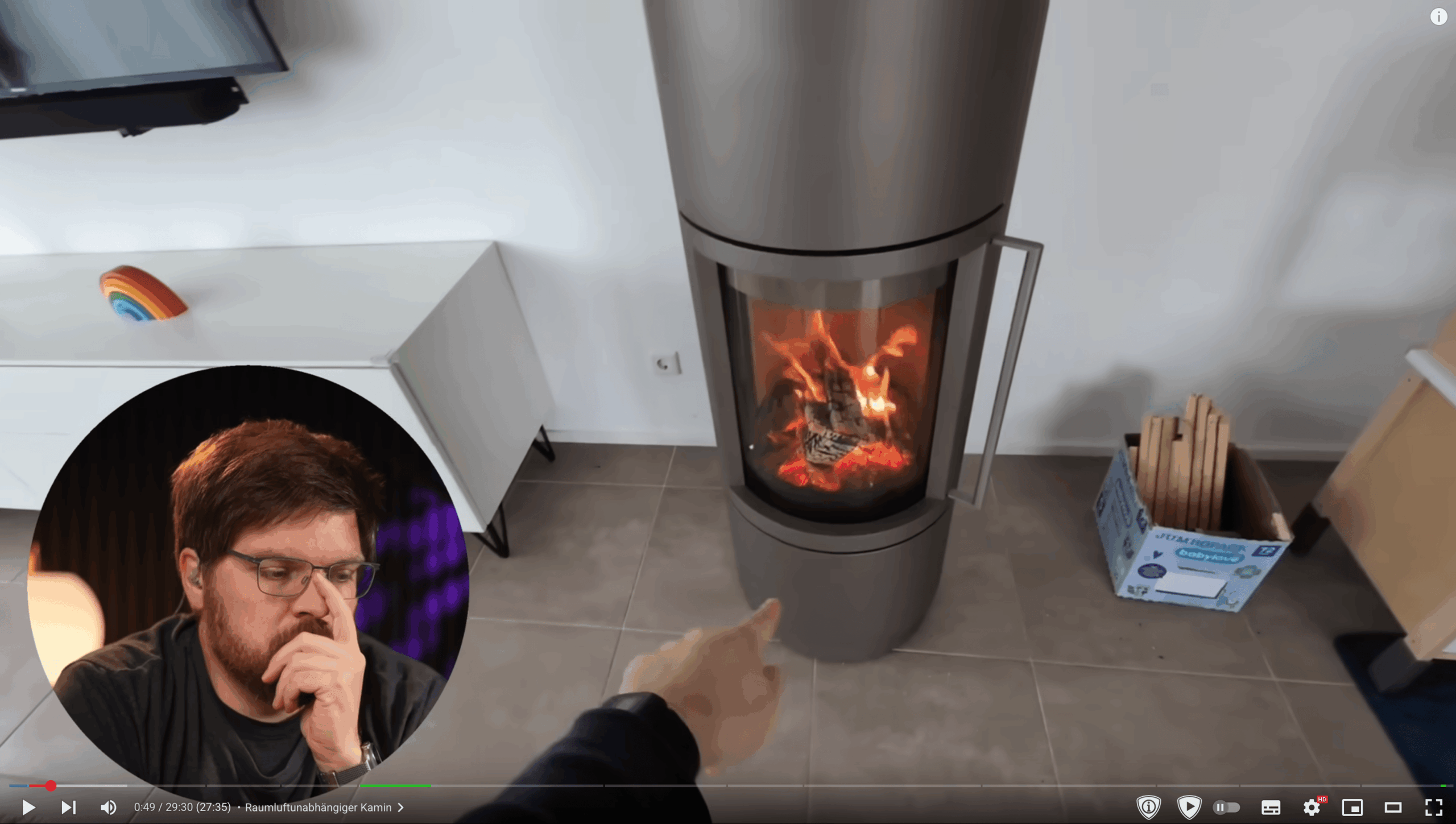
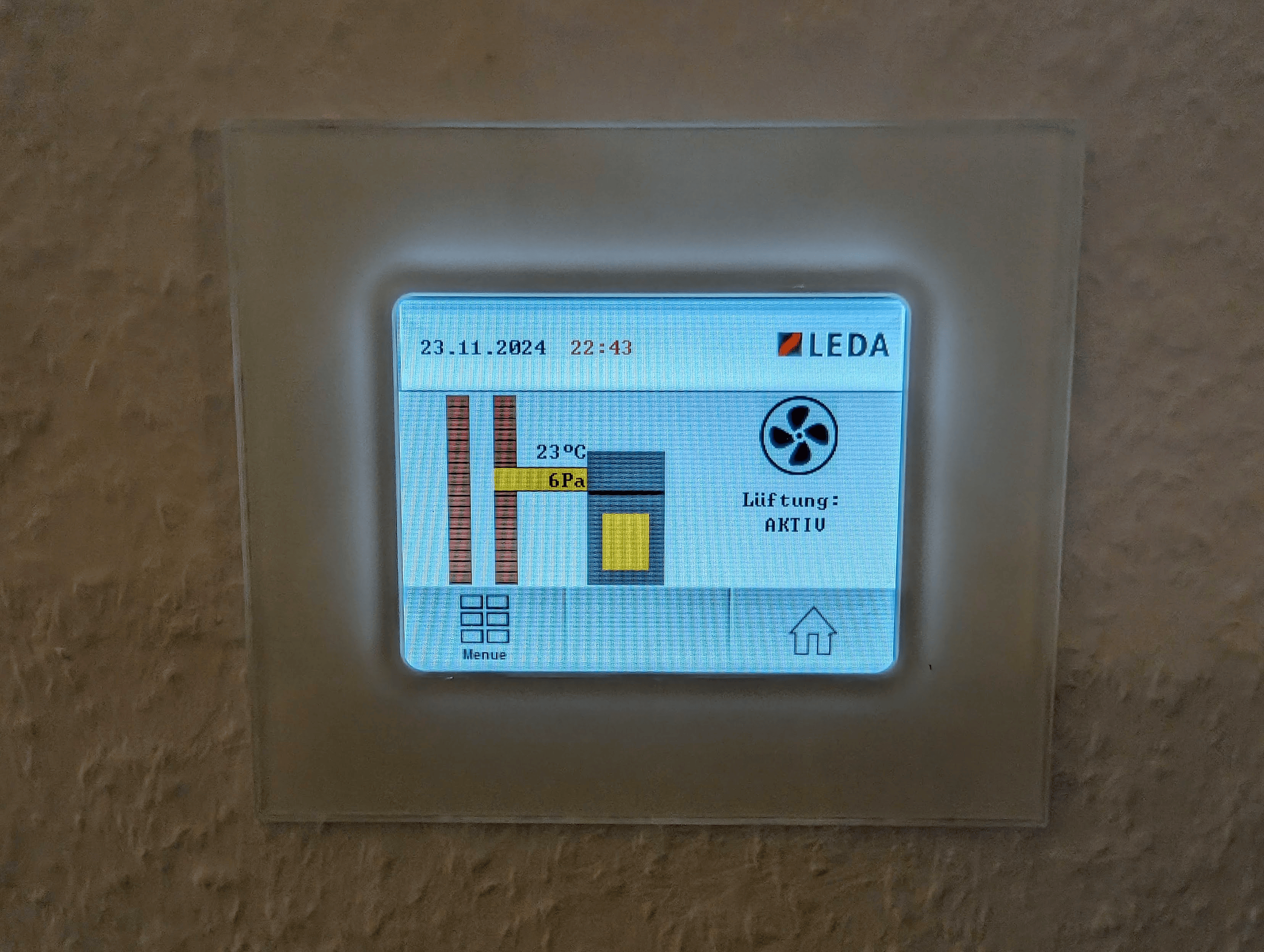
Ever since I installed a LEDA LUC2 fireplace, I wanted deeper insights into how it operates — particularly pressure difference, exhaust temperature, and ventilation state. Unfortunately, the vendor doesn’t provide any integration options, and the only external interface is a mysterious RJ12 port on the controller.
So I decided to reverse engineer it myself.
In this post, I’ll walk you through how I decoded the CAN bus communication of the LEDA LUC2, used an ESP32 with an MCP2515 module to read the values, and made them available in Home Assistant using ESPHome. Even better: the method works for any CAN-based system.
Step 1 – Sniffing the CAN Bus
I started by simply listening to the bus without sending anything. The goal was to see what kind of messages the LUC2 sends when it’s running.
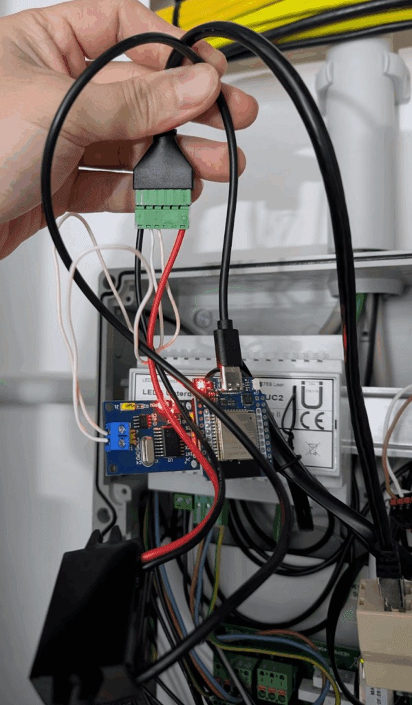
The RJ12 port on the controller exposes a CAN High / CAN Low line, so I used an MCP2515 CAN transceiver paired with an ESP32 to tap into it passively.
Required Hardware
- ESP32 Dev Board
- MCP2515 CAN module (with TJA1050 transceiver)
- RJ12 breakout or RJ12 splitter (so the main unit can keep working)
- USB-C buck converter (12 V → 5 V to power ESP32 from the fireplace)
- A few jumper wires
Step 2 – Wiring it Up
Here’s how I wired the ESP32 to the MCP2515 over SPI:
| MCP2515 Pin | ESP32 Pin |
|---|---|
| VCC | 3.3V |
| GND | GND |
| CS | GPIO16 |
| SCK | GPIO22 |
| MOSI | GPIO21 |
| MISO | GPIO17 |
| INT | Not used |
Then, I connected the CAN_H and CAN_L from the MCP2515 to the RJ12 port using a breakout cable. On the LEDA LUC2, the pinout of the RJ12 is:
| RJ12 Pin | Signal |
|---|---|
| Pin 1 | 12V (used to power the ESP32 via buck converter) |
| Pin 2 | unused |
| Pin 3 | unused |
| Pin 4 | CAN-L |
| Pin 5 | CAN-H |
| Pin 6 | GND |
⚠️ Note: Several users (including me, in early tests) accidentally swapped CAN-H and CAN-L, which results in no data being received. Make sure to get the polarity right.
Step 3 – Logging Raw CAN Frames
Once everything was connected, I flashed this minimal ESPHome YAML just to see what the fireplace was sending:
spi:
  clk_pin: GPIO22
  miso_pin: GPIO17
  mosi_pin: GPIO21

canbus:
  - platform: mcp2515
    cs_pin: GPIO16
    bit_rate: 125KBPS
    on_frame:
      - can_id: 0x28A
        then:
          - logger.log:
              format: "Raw frame: %s"
              args: [x]
I immediately started seeing messages on CAN ID 0x28A as the device is constantly measuring temperature and sending those values to it’s display. From here, I started dumping frames and inspecting the payloads over time.
Step 4 – Decoding the Messages
After collecting enough frames, I started to spot patterns:
- Messages always 8 bytes
- Byte 0 = message type
- Message Type 0x00 = sensor values
- Message Type 0x01 = status info
Example frame (Type 0x00):
00 03 E1 32 00 00 00 00- Byte 0: 00 → Type 0
- Byte 1: 03 → Pressure value
- Byte 2: E1 → Modifier / condition byte
- Byte 3: 32 → Temperature (in °C)
I decoded pressure using this logic:
float pressure = x[1] * 0.1f;
if (x[2] == 0x81) {
  pressure += 25.5f;
}
The result? Actual pressure difference values like 26.5 Pa or 29.1 Pa. Same with exhaust temperature — a direct value in °C from Byte 3.
Step 5 – Integrating Into Home Assistant
I extended the ESPHome config to publish proper sensors:
sensor:
  - platform: template
    name: "Pressure Difference"
    id: pressure_difference_sensor
    unit_of_measurement: "Pa"
  - platform: template
    name: "Exhaust Temperature"
    id: exhaust_temperature_sensor
    unit_of_measurement: "°C"

binary_sensor:
  - platform: template
    name: "Ventilation Active"
    id: ventilation_status_sensor
And the full on_frame decoding logic:
on_frame:
  - can_id: 0x28A
    then:
      - lambda: |-
          if (x.size() == 8) {
            uint8_t type = x[0];
            if (type == 0x00) {
              float pressure = x[1]*0.1f + (x[2]==0x81 ? 25.5f : 0);
              float temp = x[3];
              id(pressure_difference_sensor).publish_state(pressure);
              id(exhaust_temperature_sensor).publish_state(temp);
            } else if (type == 0x01) {
              bool vent = (x[5] == 0x01);
              id(ventilation_status_sensor).publish_state(vent);
            }
          }
As soon as ESPHome connects to Home Assistant, you’ll see these as regular sensors — ready for dashboards or automations.
Step 6 – Automation Ideas
Here are a few things I did once the data was available in Home Assistant:
- Low exhaust temperature alert: Push notification when fire needs reloading
- Auto-ventilation: Trigger fans based on pressure + ventilation status
- Trends: Long-term statistics and graphs of fireplace performance
Step 7 – Applying This to Other CAN Devices
This process works for any CAN device — not just LEDA:
- Sniff traffic using ESPHome and log raw frames
- Decode byte structure manually (you’ll get better with practice)
- Create sensors for useful values
Whether you’re working on solar inverters, EV chargers, or even cars, the approach is the same.
How Can You Discover Relevant CAN IDs on Other Devices
When applying this to other CAN systems, here’s a step-by-step process:
1. Log All CAN Traffic
Start with a generic logger in ESPHome or Arduino:
on_frame:
  - then:
      - logger.log:
          format: "ID: 0x%03X -> %s"
          args: [id, x]
Let it run for a few minutes and save the output.
2. Identify Repeating IDs
Look for:
- Periodic messages (same ID every second)
- Changing payloads (values that vary with time, temperature, input, etc.)
- Matching value changes to real-world actions
- Decoding payload bytes manually
- Iterating and testing
Final Thoughts
Reverse-engineering the LEDA LUC2 turned into a fun little weekend project — and now I have full visibility into my fireplace from anywhere. No cloud, no vendor lock-in, no guessing when to reload wood.
Everything I used is published here:
🧠 ESPHome config: 👉 https://gist.github.com/JavanXD/696d026ef202a7d6455ed4745df63e39
Enjoy the fire. 🔥
Nice work on reading the CAN Bus Data from the fireplace. I’d like to do something similar for a steam shower generator that has RJ12 ports. How did you determine that the communication protocol was a CAN bus?
Good point – in my case I actually knew it upfront from the manufacturer documentation.
great project, thanks for sharing your work.👍
Being my first ESP32 project, I learned a lot. I had to change the pin configuration for my setup which I don’t understand for the the time being… I’m going the use the pressure difference also to monitor the condition of the filter medias belonging to our ventilation system.
Love that use case,
I used the pressure difference to detect wind busts outside. It clearly shows wind busts.
Hi,
cool project, I have the same controller and want to implement it the same way. But I am not sure about the power supply. Is the 12V coming via the rj12 enough to power the esp? Because it also supplies the LUC display controller. I cannot find a specification on the power if the 12V output of the rj12 port from the LUC controller.
BR
Sebastian
Yes, I used the pin 1 and 6 from the RJ12 for the 12V.
Hi, i have used same hardware for my Schmid SMR Control. I had to put the MCP board to 3,3V, instead of 5V and swapped H/L. Frames on can_id 280 and 28B. Temperature values, PWM of pump and air throttle was found.
But after 4 hours the frames stopped. Any idea?
Congrats on your set up – nice!
As a workaround you can add a restart button to your ESPHome:
button:- platform: restart
name: "CAN-Sniffer Restart"
And have a automation triggering this button if there is no data received.
But I do not have that issue, so I don’t need it.
Hey Javan,
cool project.
I have a question about the “Pressure Difference”: it always returns a positive value, regardless of whether the air pressure is negative.
Is there a way to change that? That would be quite important for me.
Thanks!
If we know the bytes that represent the negative value we can fix it.
Unfortunately I never had negative pressure so I can’t test it.
I see.
So currently I have almost every day negative pressure values.
Would it help, when I proceed with “Step 3 – Logging Raw CAN Frames” and share the logs?
Thanks,
Stefan
Hi Stefan,
if you change the code to the following it could work:
// Extract pressure difference from Byte 2 (x[1])(x[1]); // signed 8-bit int8_t raw_pressure = static_cast
float pressure_difference = raw_pressure * 0.1f; // scale to Pa
The current pressure measurement code can never produce a negative number, because x[1] is in the range 0..255. So if the device sends negative pressure using a signed encoding (most commonly two’s complement in an 8-bit field), values that should be negative arrive as 128..255 and you display them as positive.
The new code block is trying to fix this.
Hi everyone!
Very cool project and special thanks for posting the individual steps. That was very helpful!
Can anyone please upload the communication protocols between LEDA components, ispecially master to slave?
I have a LEDA KS04 (circulation pump for water included fire place). I do not ave any other device, so there is no ongoing communication I can listen to, and the device itself does obviously not talk without trigger from a Master device. Any ideas?
Hello
unfortunately my comment was deleted somehow. Anyway, i´ll try it again.
I have the problem, that I only have a slave device. Its a KS04, the circulation pump of a fire place with water heat exchanger.
There is no Master the device speaks to, but it is possible to buy other devices like controller or sth.
I have the feeling, that the KS04 only sends data if there is a request. But I do not know hoe this request should look like. Any ideas how to find out? Can you maybe show screenshots of the protocol your master uses to talk to your slave?
Thanks in advance!
Hi Javan,
thanks for the code.
I just compiling and testing it 🙂
I’ll update, when I’ll get a negative pressure 😉
Thanks,
Stefan
Hi everyone,
I have a LEDA wood-burning stove with a water heat exchanger controlled by a Ledatronic unit (the old one without wifi), combined with a LEDATHERM KS04 water jacket module. I wanted to get all sensor data into Home Assistant, so I tapped into the internal CAN bus using an AZ-Delivery D1 Mini and an MCP2515 CAN module (125 kbps, 16 MHz crystal) + an RJ12 Jack.
Hardware wiring (D1 Mini ↔ MCP2515):
MCP2515 –> D1 Mini
SCK –> D5 (GPIO14)
SO/MISO –> D6 (GPIO12)
SI/MOSI –> D7 (GPIO13)
CS –> D8 (GPIO15)
INT –> D2 (GPIO4)
VCC –> 3.3V
GND –> GND
Instead of soldering directly to the Ledatronic PCB, I used an RJ12 splitter (Y-adapter) on one of the existing RJ12 bus cables between the Ledatronic modules. This is completely non-invasive — no board modifications, no soldering, and fully reversible.
The RJ12 connector on the Ledatronic bus carries (among others) CAN-H and CAN-L. I wired those two lines plus GND from the RJ12 splitter directly to the MCP2515 module.
Decoded CAN frames:
ID 0x281 — Main stove frame (~every 6s):
Bytes 0+1: Combustion chamber temperature (°C), 16-bit Little Endian
Byte 2: Air damper actual position (%)
Byte 3: Air damper target position (%)
Byte 4: Operating state
Code State
0x00 Standby
0x01 Door closed
0x02 Cold start / Kindling
0x03 High heating
0x04 Normal heating
0x07 Embers
0x08 Embers part-load
0x09 Part-load operation
0x61 Heating fault
0xE2 Door open
ID 0x288 — LEDATHERM KS04 water jacket (~every 6s):
Byte 1: Buffer temperature top (°C)
Byte 2: Buffer temperature bottom (°C)
Byte 3: Water jacket temperature (°C)
Byte 4: Pump power (%)
ID 0x28A — Sensor data (multiple subtypes per second):
Subtype 0x00: x = draught pressure (Pa), x = flue gas temperature (°C)
Subtype 0x01: x = ventilation active flag
ESPHome YAML (full config below ### signs — just add your secrets):
### YAML START ###
substitutions:
name: kachelofen
friendly_name: Kachelofen
esphome:
name: ${name}
friendly_name: ${friendly_name}
min_version: 2023.6.0
esp8266:
board: d1_mini
# Logging auf DEBUG damit alle CAN-Frames in der Konsole erscheinen
logger:
level: DEBUG
baud_rate: 115200
# Home Assistant API
api:
encryption:
key: !secret api_key
# OTA-Updates
ota:
platform: esphome
password: !secret ota_password
# WLAN
wifi:
ssid: !secret wifi_ssid
password: !secret wifi_password
min_auth_mode: WPA2
captive_portal:
# Optionaler Webserver (Logs auch im Browser erreichbar)
web_server:
port: 80
# SPI-Bus – Hardware-Pins des D1 Mini
spi:
clk_pin: GPIO14 # D5
miso_pin: GPIO12 # D6
mosi_pin: GPIO13 # D7
canbus:
– platform: mcp2515
id: can_bus
cs_pin: D8
can_id: 0x000
bit_rate: 125kbps
on_frame:
# =========================================================
# ID 0x281 – Ofen-Hauptframe (alle ~6s)
# Byte 0+1: Feuerraumtemperatur °C, 16-bit Little Endian
# Byte 2: Luftklappe Ist-Position (%)
# Byte 3: Luftklappe Soll-Position (%)
# Byte 4: Betriebszustand (Status-Codes s.u.)
# Byte 5-7: Konstant (weitere Aktoren, falls vorhanden)
# =========================================================
– can_id: 0x281
then:
– lambda: |-
// — Feuerraumtemperatur (16-bit Little Endian) —
float feuerraum = (float)((uint16_t)x[0] | ((uint16_t)x[1] << 8));
id(sensor_ofen_feuerraum_temp).publish_state(feuerraum);
// — Luftklappe —
id(sensor_ofen_klappe_ist).publish_state((float)x[2]);
id(sensor_ofen_klappe_soll).publish_state((float)x[3]);
// — Betriebszustand —
uint8_t status = x[4];
switch (status) {
case 0x00:
id(sensor_ofen_betriebszustand).publish_state("Bereit");
break;
case 0x01:
id(sensor_ofen_betriebszustand).publish_state("Tür wurde geschlossen");
break;
case 0x02:
id(sensor_ofen_betriebszustand).publish_state("Anheizen Kaltstart");
break;
case 0x03:
id(sensor_ofen_betriebszustand).publish_state("Heizbetrieb Hochheizen");
break;
case 0x04:
id(sensor_ofen_betriebszustand).publish_state("Heizbetrieb");
break;
case 0x07:
id(sensor_ofen_betriebszustand).publish_state("Grundglut");
break;
case 0x08:
id(sensor_ofen_betriebszustand).publish_state("Grundglut Teillast");
break;
case 0x09:
id(sensor_ofen_betriebszustand).publish_state("Teillastbetrieb");
break;
case 0x61:
id(sensor_ofen_betriebszustand).publish_state("Heizfehler");
break;
case 0xE2:
id(sensor_ofen_betriebszustand).publish_state("Tür geöffnet");
break;
default: {
char buf[20];
snprintf(buf, sizeof(buf), "Unbekannt (0x%02X)", status);
id(sensor_ofen_betriebszustand).publish_state(buf);
break;
}
}
# =========================================================
# ID 0x288 – LEDATHERM KS04 / Wassertasche (alle ~6s)
# Byte-Zählung im Forum 1-basiert → hier 0-basiert:
# x[1] = Speichertemperatur oben (°C)
# x[2] = Speichertemperatur unten (°C)
# x[3] = Temperatur Wassertasche (°C)
# x[4] = Pumpenleistung (%)
# =========================================================
– can_id: 0x288
then:
– lambda: |-
id(sensor_ofen_speicher_oben).publish_state((float)x[1]);
id(sensor_ofen_speicher_unten).publish_state((float)x[2]);
id(sensor_ofen_wassertasche).publish_state((float)x[3]);
id(sensor_ofen_pumpe).publish_state((float)x[4]);
# =========================================================
# ID 0x28A – Sensor-Daten (Subtyp via x[0])
#
# Subtyp 0x00:
# x[1] = Zugdruck (Pa)
# x[3] = Abgastemperatur (°C)
#
# =========================================================
– can_id: 0x28A
then:
– lambda: |-
if (x[0] == 0x00) {
float pressure = x[1]*0.1f + (x[2]==0x81 ? 25.5f : 0);
id(sensor_ofen_zugdruck).publish_state(pressure);
id(sensor_ofen_abgas_temp).publish_state((float)x[3]);
} else if (x[0] == 0x01) {
bool vent = (x[5] == 0x01);
id(binary_sensor_ofen_lueftung_aktiv).publish_state(vent);
}
# =========================================================
# BINARY SENSOREN
# =========================================================
binary_sensor:
– platform: template
id: binary_sensor_ofen_lueftung_aktiv
name: "Lüftung aktiv"
# =========================================================
# SENSOREN
# =========================================================
sensor:
# — Ofen (0x281) —
– platform: template
id: sensor_ofen_feuerraum_temp
name: "Brennraumtemperatur"
unit_of_measurement: "°C"
device_class: temperature
state_class: measurement
icon: "mdi:fire"
accuracy_decimals: 0
filters:
– delta: 0.5
– platform: template
id: sensor_ofen_klappe_ist
name: "Luftklappe Ist-Position"
unit_of_measurement: "%"
state_class: measurement
icon: "mdi:valve"
accuracy_decimals: 0
filters:
– delta: 0.5
– platform: template
id: sensor_ofen_klappe_soll
name: "Luftklappe Soll-Position"
unit_of_measurement: "%"
state_class: measurement
icon: "mdi:valve"
accuracy_decimals: 0
filters:
– delta: 0.5
# — Speicher & Wassertasche (0x288) —
– platform: template
id: sensor_ofen_speicher_oben
name: "Speichertemperatur oben"
unit_of_measurement: "°C"
device_class: temperature
state_class: measurement
icon: "mdi:thermometer-chevron-up"
accuracy_decimals: 0
filters:
– delta: 0.5
– platform: template
id: sensor_ofen_speicher_unten
name: "Speichertemperatur unten"
unit_of_measurement: "°C"
device_class: temperature
state_class: measurement
icon: "mdi:thermometer-chevron-down"
accuracy_decimals: 0
filters:
– delta: 0.5
– platform: template
id: sensor_ofen_wassertasche
name: "Wassertasche Temperatur"
unit_of_measurement: "°C"
device_class: temperature
state_class: measurement
icon: "mdi:thermometer-water"
accuracy_decimals: 0
filters:
– delta: 0.5
– platform: template
id: sensor_ofen_pumpe
name: "Pumpenleistung"
unit_of_measurement: "%"
state_class: measurement
icon: "mdi:pump"
accuracy_decimals: 0
filters:
– delta: 0.5
# — Zugdruck & Abgas (0x28A) —
– platform: template
id: sensor_ofen_zugdruck
name: "Zugdruck"
unit_of_measurement: "Pa"
device_class: pressure
state_class: measurement
icon: "mdi:gauge"
accuracy_decimals: 0
filters:
– delta: 0.5
– platform: template
id: sensor_ofen_abgas_temp
name: "Abgastemperatur"
unit_of_measurement: "°C"
device_class: temperature
state_class: measurement
icon: "mdi:smoke"
accuracy_decimals: 0
filters:
– delta: 0.5
# =========================================================
# TEXT SENSOREN
# =========================================================
text_sensor:
– platform: template
id: sensor_ofen_betriebszustand
name: "Betriebszustand"
icon: "mdi:fire-circle"
### YAML – END ###
Notes:
All sensor IDs use the sensor_ofen_ prefix to keep things tidy in HA.
filters: – delta: 0.5 on every sensor prevents HA from being flooded with updates — values are only published when they actually change. The 0x28A frame arrives several times per second, so this filter makes a real difference.
Status codes were originally documented by Wohnmaschine and Morpheus on the FHEM/Homematic community forums back in 2020 — big credit to them for the groundwork.
Happy to answer questions if you have the same setup.
Feel free to adjust the wording or add your name/handle before posting!
Amazing, thanks for the share!
filters: – delta: 0.5is a good idea!